How to Clear Tesla 1512876-00-B Airbag SRS Crash using Xtool step-by-step?
What You’ll Need
- XTOOL diagnostic tablet with compatible EV diag software (Xtool D9EV, Prodigy, Compass, Compass Master etc)
- VCI (Vehicle Communication Interface) box
- OBD (On-Board Diagnostics) cable
- 12V power supply (e.g., cigarette lighter adapter)
- Universal jumper cables with labeled ends (ground, 12V, CAN high, CAN low)
- The Tesla airbag module itself (removed from the vehicle)

Step 1: Hardware Setup
Connect the VCI box
Start
by plugging the OBD cable into the VCI box. Then, supply power to the
VCI box using a 12V source—a cigarette lighter adapter works perfectly.
Press the power button on the VCI box; it will automatically pair with
the XTOOL tablet via wireless or Bluetooth connection.


Prepare the airbag module
Place the airbag module on your workbench in a specific orientation—exactly as shown in the tool’s wiring diagram. Do not position it any other way, as correct pin alignment depends on this placement.
Step 2: Identify the Correct Part Number
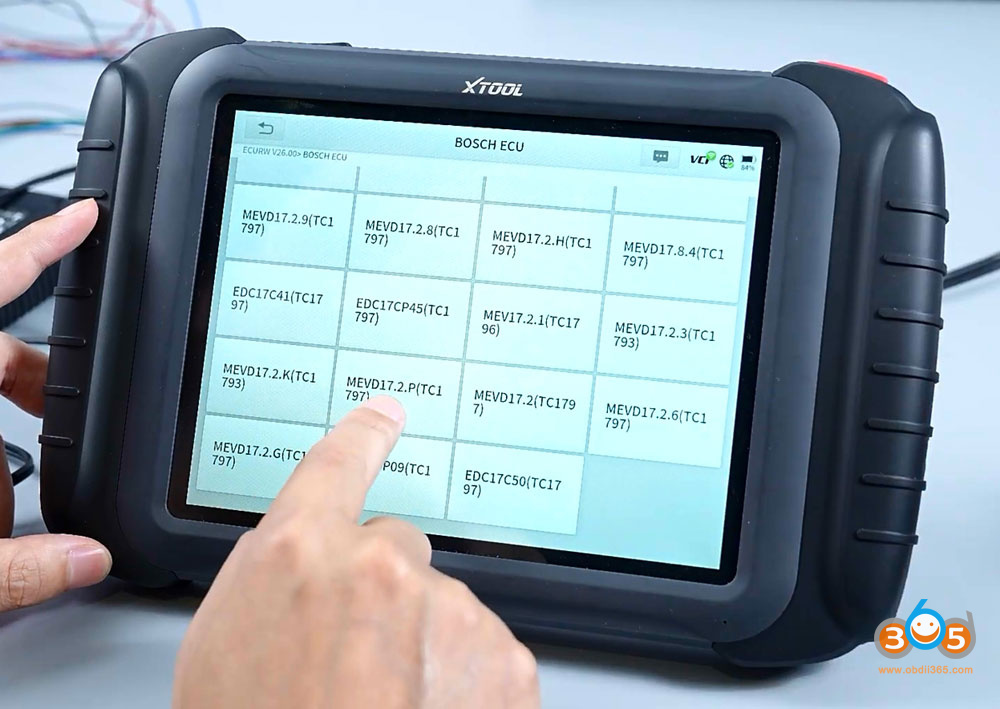
On the tablet, navigate to Component Test and select Airbag Repair (the first option). Choose Tesla from the manufacturer list. Now, locate the physical part number on your airbag module (it is printed on the label, here the SRS part number is 1512876-00-B). Cross-check this number with the tablet’s displayed list to ensure you select the exact match. In the example provided, the matching part number was clearly identified on the screen.


Step 3: Understand the Wiring Diagram
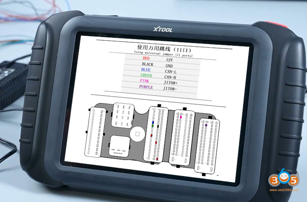
Before connecting any cables, tap the wiring diagram icon in the top right corner of the tablet. This diagram is critical—it shows exactly which pins on the module correspond to:
- 12V power supply
- Ground
- CAN high
- CAN low
In this case, there are only four cables to connect, located at specific pins on the module.

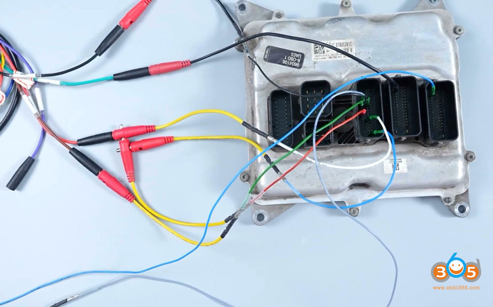
Step 4: Connect the Jumper Cables
Use the universal jumper cables that come with your kit. Here is an important practical tip:
If a jumper pin feels loose when inserted, gently press the metal part of the connector with pliers or a small tool. This will tighten the grip so it fits as securely as a new cable.
Now, follow the wiring diagram exactly:
- Connect the ground cable to its designated pin.
- Connect the 12V cable to its pin.
- Connect the CAN high cable to its pin.
- Connect the CAN low cable to its pin.
Crucial note: The color of the cable insulation is for reference only. Do not rely on color matching. Instead, read the label printed on each cable (e.g., "CAN H", "CAN L", "GND", "12V") to ensure correct connections.


Step 5: Link to the VCI Box
Once all four jumper cables are firmly attached to the airbag module, connect the other ends to the OBD cable that runs from the VCI box. The order here does not matter as long as each labeled cable goes into the corresponding port on the OBD breakout connector.

Step 6: Perform the Reset on the Tablet
Return to the XTOOL tablet’s main menu. Select the Airbag System option, then choose Special Function. From the submenu, select Clear Collision Records.
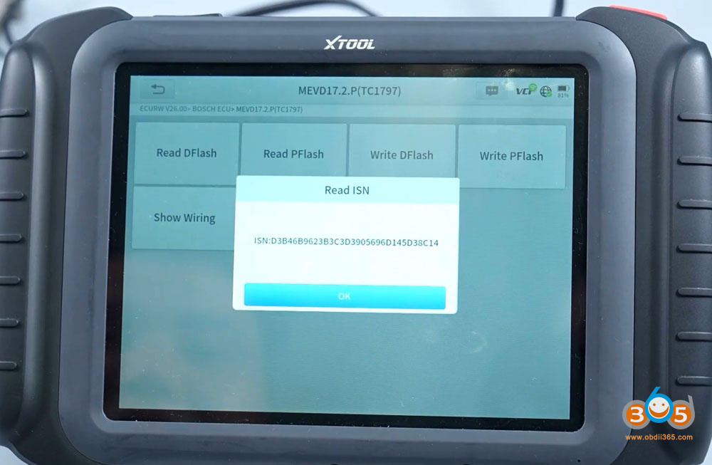
The tablet will process the command. Within seconds, a confirmation message appears: "The collision record was cleared successfully."


Final Verification
That’s it. The crash data is now erased from the module’s memory. The module can be reinstalled in the vehicle, and the airbag system will function without stored collision codes—provided all physical components (sensors, airbags, seatbelts) are also repaired or replaced as needed.
Key Takeaways for Accuracy
Always verify the part number before proceeding.
Follow the wiring diagram precisely—pin location matters more than wire color.
Ensure tight connections using the pin-tightening tip.
The reset function is a single-click operation once hardware is correctly set up.
This method, demonstrated with the XTOOL diagnostic tool, turns a potentially confusing repair into a quick, repeatable procedure.